|

Binary Convolutional Codes
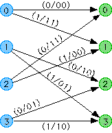
BCC Trellis:
At the heart of the Viterbi decoding algorithm is the trellis which is an extension of the encoder state machine that shows the passage of time. A section of the trellis shows the possible state transitions and output codewords for one period of the encoder. A section of the trellis for the code in the previous examples is shown below. The blue circles are the current state and the green circles are the next state.
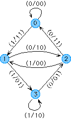
Encoder Finite Stage Machine:
As previously mentioned, the encoder can be represented as a finite state machine with outputs as functions of the current state and input. The state machine for the encoder in figure 1 is shown below. The message/codeword combinations associated with each branch are shown in the following format: (message word/codeword) where both words are written from left to right starting with the least significant bit. This is the same format that is used by the workshop.
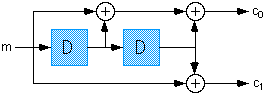
Encoder Structure
In the BCC encoder, message bits are fed into a shift register. The set of delay elements in the shift register can be thought of as a state machine which has 2^d possible states where d is the number of delay elements in the register. Codeword bits are generated as functions of the current state and input. These functions are sums of fixed patterns of taps into the shift register. What is referred to as a codeword here is not the same as in block coding. In block coding, each block is independent of all other blocks, this is not so for BCCs. Each codeword is dependent on the current message word and the state of the register which stores information about the past values of the message bits. Therefore successive codewords are not independent of one another. An example of an encoder circuit is show below for a rate 1/2 code. The state naming convention used here and in the workshop is that the first delay element that the message is fed into is the least significant bit of the shift register whose contents represent the state.
Encoder Transfer Function Matrix:
We have been representing the code used in the examples as: G(D) = [(1+D+D^2),(1+D^2)]. G(D) is called the transfer function matrix of the code. It is just another way of representing the construction of the encoder. The first expression (1+D+D^2) is for the first codeword bit(C0). It is in the form of a finite impulse response(FIR) function. It means that bit C0 is equal to the sum of the current message bit plus the message bit's value one period ago plus the message bit's value two periods ago. Infinite impulse response(IIR) filters can also be represented this way, but they would be rational functions of D. Note: the workshop presently does not support IIR transfer functions.
The term "transfer function" is borrowed from the Digital Signal Processing field. It is the ratio of output to input; G(D) = C(D)/M(D) where C(D) is the codeword and M(D) is the message word.
When the transfer function used above is substituted into the equation, the equation for the first codeword bit becomes:
C(D) = M(D)*G(D)
we get the following equation:
C(D) = M(1)+M(D)+M(D^2)
This is the same as the following difference equation:
C(n) = M(n)+M(n-1)+M(n-2)
which just states what we previously said about how to calculate the first codeword bit.
Message Words and Codewords:
The codewords in BCCs are the collection of code bits that form the output of the encoder circuit for one period of the shift register. Likewise a message word is the collection of bits inputed to the encoder circuit during one period of the shift register. Message words can be any length(greater than 0) although they are usually just one bit long. The codeword length should be greater than the message length otherwise no redundancy is added and the code has no error correcting capability. The rate of a BCC is computed the same way as with block codes. It is the ratio of the message word length to the codeword length. Instead of representing the rate in the form (n,k,dmin), the rate of a BCC is written k/n. The BCC analog of the minimum distance of a block code is the free distance which is defined as the number of state changes that give a minimum weight codeword sequence.
Relationship to Block Codes:
Block codes such as Hamming codes and Reed-Solomon codes break a message stream up into fixed size blocks and add redundancy symbols to offer error correction capability. They are usually decoded via algebraic methods.
Binary convolutional codes take a different approach to error control coding. The message stream is not broken up into blocks with redundancy added to each block independently. Instead, redundancy is added continuously and is dependent on past bits of the message. This converts the entire message stream into one long codeword. Note that this use of the term "codeword" is not the same as the meaning we will use for the rest of our discussion of BCCs and the Viterbi algorithm. One further difference between block codes and convolutional codes is that BCCs are also decoded by a heuristic approach rather than algebraically.
|

